HOW A BELLOWS WORKS
Metal bellows are designed to absorb thermal and/or mechanical movements in piping or ducting systems while retaining system operating pressure at system temperature. Bellows can absorb the following movements:

Whereas metal bellows can be designed to resist torsional loads, metal bellows cannot tolerate torsional movement. Metal bellows must be designed to avoid system resonant vibration frequency (if vibration exists) in order to prevent immediate mechanical bellows failure. Failure to specify torsion or vibration (if either exists) can result in immediate bellows failure.
BELLOWS PRESSURE THRUST
Metal bellows cannot restrain longitudinal pressure loads without integral restraining hardware such as tie rods, hinges, gimbals or external pipe anchors. Longitudinal pressure loads on a bellows results in "pressure thrust". Pressure thrust force is created by the system and/or test pressure acting on the area of the "mean diameter" of the bellows. (Bellows mean diameter = bellows convolution I.D. + ((O.D - I.D)/2 ). A pressurized, unrestrained metal bellows expansionjoint in a piping system without anchors will elongate (extend) due to pressure thrust which can result in immediate bellows "squirm" and failure. Pressure thrust forces are typically higher than all other system forces combined.
BELLOWS PRESSURE STRESSES
Pressure applied to a bellows is limited by "Hoop Stress" (EJMA S2) and "Bulge Stress" (EJMA S4). Hoop Stress runs circumferentially around the bellows resulting from pressure differential between the inside and outside diameter of the bellows. Hoop stress is what holds a bellows together similar to hoop rings on a wood barrel. Hoop stress must be held to code allowable levels. Bulge Stress runs longitudinal to the bellows centerline acting on the sidewall of the bellows convolutions. Bulge Stress is also calculated to code.
Understanding Metal Bellows Pressure Thrust is Extremely Important
With rigid pipe installed between two flanges - pressure thrust is restrained by the strength of the pipe.
With a thin wall convoluted bellows welded to two flanges, the bellows reaction to pressure thrust results in the bellows growing in length until the bellows "squirms" and/or the convolutions stretch out to become the tube from which they were formed.
METAL BELLOWS PRESSURE RETAINING CAPABILITY
Metal bellows are designed to retain loads imposed by internal and/or external system pressure and/or test pressure. Bellows convolution geometry, number of convolutions, material type and material thickness all affect bellows pressure retaining capability.
Over pressurization and/or improper guiding of a metal bellows expansion joint can cause the bellows to "squirm". Squirm can lead to permenant deformation and/or immediate failure of the bellows.
METAL BELLOWS SPRING RATE
In addition to longitudinal pressure thrust loads, movement within a bellows requires a "force" to cause the bellows to compress, extend or angulate. Bellows "spring rate" is a design consideration. To calculate the load (force) imposed on equipment adjacent to the expansion joint, use the equation below.
F = K x X
F - The load (force) imposed on equipment on either side of the bellows.
K - The bellows spring rate (expressed as pounds/inch of movement for axial and lateral movements, and inch/pound per degree for angular movement)
X - The anticipated or specified movement
The result is referred to as "spring force". For a bellows expansion joint without integral longitudinal pressure restraining hardware, one must add the bellows spring force to the pressure thrust force to determine the total force imposed on adjacent equipment or pipe anchors. Other loads that must be considered are dead weight, frictional, wind, etc.
METAL BELLOWS CYCLE LIFE
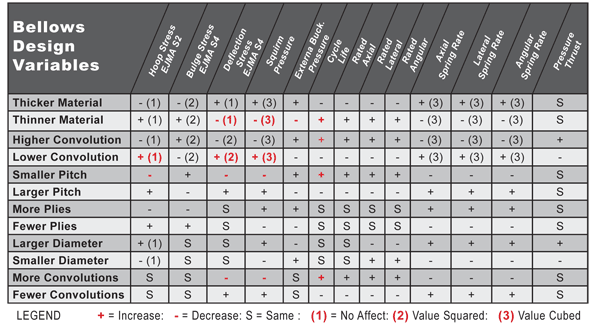
When a bellows compresses, extends or angulates, the movement is absorbed by deformation of the side walls of the bellows convolutions. The stress caused by the movement is referred to as the bellows deflection bending stress (EJMA S6). This stress is highest at the "crest" and "root" of the bellows convolution. Metal bellows are designed to function with a deflection bending stress value that far exceeds the yield strength of the bellows material. Therefore, most metalexpansion joints are designed to deflect in the "plastic" range of materials and the bellows will take a permanent "set" at the rated bellows movements. Bellows are rarely designed to operate in the elastic range of materials. Bellows operating in the plastic material range will eventually fail due to fatigue after a finite number of movement cycles. Realistic cycle life should be specified for bellows design. As the chart on page 26 shows, the higher the cycle life, the "weaker" the bellows design pressure capability. The "safest" bellows design results from real-world cycle life, pressure, movement and temperature data.
BELLOWS DESIGN VARIABLES & THEIR RELATIONSHIP TO BELLOWS DYNAMICS

The chart above shows the complexity of bellows design with the relationship of bellows geometry, material thickness, pressure and movement. Optimum bellows design requires actual pressure and temperature to be specified along with actual calculated thermal movement to be absorbed by the bellows. Overstating system data will result in a less safe bellows design. Most system designers think that specifying an extended bellows cycle life increases system reliability, whereas a longer than necessary specified bellows cycle life in most cases has the opposite result. As the chart above shows, the relationship between cycle life and pressure stability is a "balancing act". The higher the cycle life, the lower the pressure retaining capability of a given bellows design. Note the red values in the chart, when cycle life is higher, squirm pressure is lower.
The Standards of the Expansion Joint Manufacturers Association (EJMA) covers the subject of bellows cycle life very well and Lortz recommends that system designers refer to the latest edition of the EJMA Standards.
COMMON BELLOWS MATERIALS
Bellows material selection is determined through knowledge of the system process and media. Responsibility for the selection of bellows materials is that of the system process designer or end user.
BELLOWS FORMING
Typical Expansion Joint Applications
Axial Movement Only
|
Combined Movements
|
Angular Movements
Hinge & Gimbal
|
|